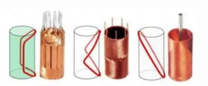
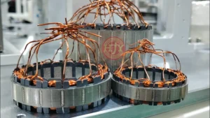
An integrated automation solution covering core loading, precision winding, stator segment assembly and round forming, joining, and inspection.
As industrial servo systems, CNC machine tools, robotic joints, and high-precision automation equipment demand faster response, greater operating stability, and higher power density, the consistency of stator windings, the accuracy of segment assembly, and the control of electrical performance have become increasingly important.
A segmented stator is produced by winding individual stator teeth or linked tooth segments separately and then assembling them into a complete stator. Compared with a one-piece stator, this structure provides more flexibility for improving winding-space utilization and producing high-density windings. It also introduces additional process challenges, including core positioning, crossover-wire management, automated segment assembly, joining and fixation, and dimensional control.
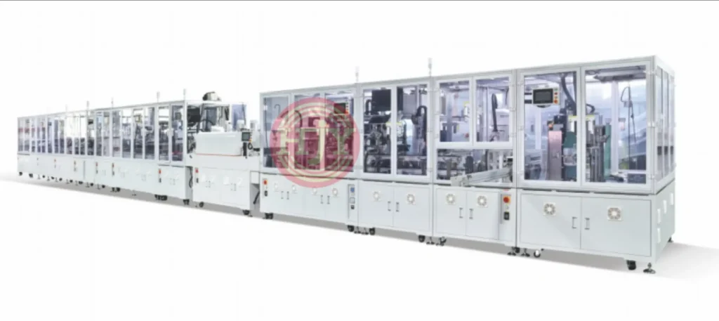
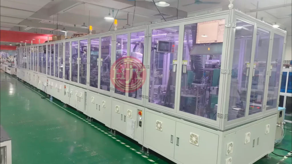
To address these requirements, JHY provides fully automatic production lines for segmented servo motor stators. Winding, transfer, segment assembly, joining, inspection, and traceability are integrated into a unified automation system and configured according to the customer’s product structure, process requirements, and target capacity.
1. Key Challenges in Automated Segmented Stator Production
Producing segmented stators is not simply a matter of combining a winding machine, a round-forming station, and inspection equipment. Product status, positioning references, and cycle times across all processes must be planned as one system to ensure stable line operation.
1.1 Winding Arrangement and Tension Control
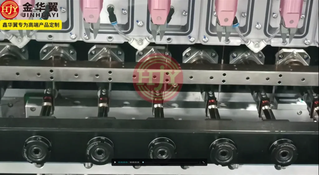
Magnet-wire tension must remain stable throughout the winding process. Excessive tension may stretch the wire, damage the enamel insulation, or alter coil dimensions. Insufficient tension may result in loose turns, overlapping wires, or unstable winding patterns.
Different wire diameters, turn counts, winding structures, and speeds require corresponding tension settings. Start-up, normal winding, direction reversal, and wire finishing may also require separate control parameters.
1.2 Start Wire, Finish Wire, and Crossover-Wire Handling
Segmented stators commonly require controlled handling of the start wire, finish wire, hook points, and crossover wires between adjacent teeth. The length and routing of these wires affect both the winding process and subsequent segment assembly and terminal connection.
If adjacent core segments contain cross-slot connections or long crossover wires, dedicated wire-protection and guiding mechanisms may be required during automatic transfer and assembly.
1.3 Segment Positioning and Roundness Control
A stator consists of multiple individual teeth or linked tooth segments. Dimensional variation in each segment can accumulate during assembly. The fixture must therefore be selected according to the product structure and may reference the inner diameter, outer diameter, or individual tooth geometry. Key characteristics include roundness, concentricity, inter-tooth gaps, and overall height.
1.4 Automated Transfer Between Stations
After winding, each core segment carries both a coil and lead wires. Grippers and transfer mechanisms must avoid the winding and end turns to prevent wire impact, compression, deformation, and positioning errors.
1.5 Inspection Criteria and NOK Handling
Clear acceptance criteria are required for resistance, surge, insulation, appearance, and dimensional inspections. Inspection results should also be linked to product identification, station data, and NOK sorting logic to establish a complete quality-control process.
2. Typical Automated Production Process
Depending on the product structure and process requirements, a segmented servo motor stator line may include the following operations:
Core Loading → Insulator Assembly → Precision Winding → Lead-Wire Handling → Automatic Transfer
→ Stator Segment Assembly and Round Forming → Joining or Fixing → Electrical Testing →
Vision Inspection → OK Product Unloading
The actual process sequence is determined by the stator structure, winding path, connection method, and assembly requirements.
For example:
- Insulators may be preassembled by the supplier or installed at an automatic assembly station.
- End connections may use soldering, resistance welding, laser welding, crimping, or another process, depending on the product.
- After round forming, the stator may be welded directly, press-fitted into a housing, or secured with a retaining ring.
- Inspection and traceability functions can be configured to the customer’s quality standards.
3. Core Process Capabilities
3.1 Precision Winding and Multi-Stage Tension Control
The winding station controls turn count, winding direction, wire path, and lead-wire position according to the product drawing. Separate tension parameters can be assigned to acceleration, normal winding, direction reversal, and wire finishing to maintain stable wire behavior throughout the cycle.
Depending on the product, the winding station may also support:
- Single-wire or multi-wire parallel winding
- Automatic start-wire and finish-wire handling
- Automatic wire hooking
- Crossover-wire control
- Automatic tape wrapping
- Wire-break or missing-wire detection
- Turn-count monitoring
- Wire-tail detection
The final configuration must be evaluated against the wire diameter, winding structure, and required cycle time.
3.2 Automatic Segment Assembly and Round Forming
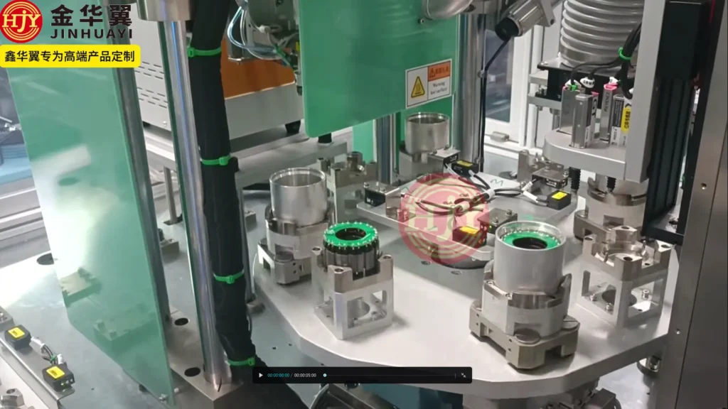
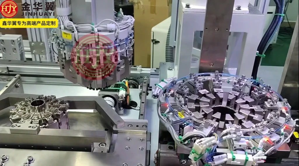
At this station, wound individual teeth or linked tooth segments are loaded into a fixture in the specified sequence. Round forming is then completed through synchronized clamping or individual segment positioning.
Depending on the critical product dimensions, the system may use:
- Outer-diameter positioning
- Inner-diameter positioning
- Individual tooth positioning
- Combined inner- and outer-diameter positioning
- Cage-type round-forming fixtures
- Individually clamped segment assembly fixtures
For products with demanding roundness and tooth-position requirements, individual segment positioning can constrain each core segment separately during assembly.
Final assembly accuracy depends on core dimensional tolerances, fixture design, positioning references, clamping method, and deformation during subsequent welding or press-fitting. These factors must be evaluated using product drawings and samples.
3.3 Flexible Automated Transfer
Robots or dedicated transfer mechanisms move workpieces between stations. The gripping system is customized to the core geometry and winding position, minimizing direct contact with the magnet wire and end turns.
Combined with vision guidance, fixture identification, and in-position detection, the transfer system may provide:
- Workpiece orientation recognition
- Automatic pick-and-place
- Fixture-position confirmation
- Missing-part or double-loading detection
- Program changeover for different product models
- Isolation of abnormal workpieces
3.4 Joining and Terminal Connection
Depending on the product design, the line may integrate soldering, resistance welding, laser welding, or another terminal-connection process.
The joining station may be configured with:
- Joining-position control
- Process-parameter management
- Join-result evaluation
- Electrode-life management
- Joining-area cleaning
- Fume or exhaust treatment
- Automatic NOK sorting
The joining method and inspection criteria must be defined according to terminal material, magnet-wire specification, connection geometry, and the customer’s process requirements.
4. In-Line Inspection and Quality Control
Electrical, vision, and dimensional inspection stations can be incorporated into a segmented stator line to provide in-process quality monitoring.
4.1 Electrical Testing
Optional test items include:
- Winding resistance
- Surge or interturn testing
- Insulation resistance
- Hipot testing
- Phase-to-phase consistency
- Open-circuit or short-circuit detection
Temperature acquisition and resistance compensation can also be added when required by the project.
4.2 Vision Inspection
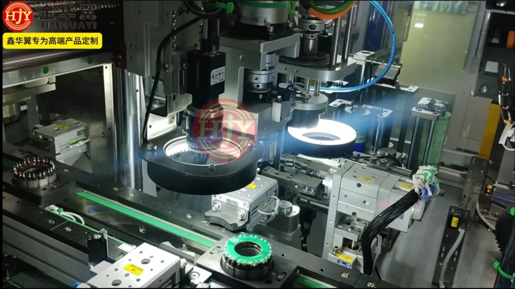
A CCD vision system may inspect:
- Winding appearance
- Crossover wires, overlapping turns, and loose wires
- Start-wire and finish-wire positions
- End-winding height
- Joint appearance
- Wire intrusion into restricted areas
- Product model and orientation
- Missing or incorrectly assembled components
Vision-inspection capability depends on the defect characteristics, imaging angle, lighting conditions, and the customer’s acceptance criteria. During project evaluation, customers should provide OK samples, NOK samples, and defect-classification requirements.
4.3 Dimensional Inspection
Depending on the product requirements, displacement sensors, contact measurement, or vision measurement may be used to inspect:
- Stator inner and outer diameters
- Overall height
- Roundness after segment assembly
- End-winding height
- Joining position
- Critical assembly dimensions
After inspection, OK and NOK products can be separated automatically to prevent non-conforming parts from entering subsequent processes.
5. Flexible Changeover and Line Expansion
JHY applies a modular design approach, configuring winding fixtures, round-forming fixtures, grippers, and process programs for each stator model.
For products with similar structures, changeover may involve:
- Replacing product fixtures
- Replacing robot grippers
- Adjusting wire-guiding and tension parameters
- Loading the corresponding production program
- Switching the vision-inspection recipe
- Switching electrical test parameters
Whether one line can accommodate multiple models must be evaluated according to stator dimensions, tooth geometry, wire diameter, turn count, assembly method, and inspection requirements.
The line may also reserve interfaces for future expansion, including:
- Automatic joining
- Stator press-fit into housing
- Potting or adhesive dispensing
- Laser marking
- Barcode scanning
- MES integration
- Automatic packaging
6. Production Data and MES Traceability
Depending on the customer’s digital manufacturing requirements, the line can use barcodes, QR codes, or other product-identification methods and record critical process and inspection data.
Traceable data may include:
- Product model and batch
- Winding turn count
- Tension parameters
- Winding-program version
- Joining parameters
- Resistance and electrical test results
- Vision-inspection results
- Equipment alarm records
- Production time
- OK or NOK status
Integration with the customer’s MES or production-management system can support production-data queries, equipment-status monitoring, quality traceability, and batch management.
Communication protocols, data fields, and system interfaces should be agreed jointly at the beginning of the project.
7. Customer Value of the Automated Line
7.1 Improved Product Consistency
Program-controlled winding, automatic positioning, and standardized process control reduce variations associated with manual operations and help maintain consistent winding structures, assembled dimensions, and electrical performance.
7.2 Reduced Intermediate Handling
Integrating winding, segment assembly, joining, and inspection into one production line reduces manual handling and repeated clamping, lowering the risk of part damage, coil deformation, and positioning errors.
7.3 Higher Production Efficiency
Multi-station coordination, automatic loading and unloading, and robotic transfer reduce waiting time and allow each station to operate continuously according to the overall line cycle.
7.4 Reduced Dependence on Manual Labor
Automation performs repetitive winding, handling, inspection, and sorting tasks, reducing reliance on skilled operators and minimizing quality variation caused by manual operations.
7.5 Support for Flexible Production
Modular stations, replaceable tooling, and recipe management allow the equipment to switch between products according to order requirements and support multi-model, batch-based production.
7.6 Stronger Quality Traceability
Process parameters and inspection results can be linked to a product batch or unique identifier, providing data for quality analysis, exception tracking, and production management.
8. Applicable Products and Industries
The automated line is primarily suitable for:
- Segmented servo motor stators
- Frameless motor stators
- Robotic joint motor stators
- Industrial servo motors
- CNC machine-tool motors
- Motors for automated actuators
- Other stator products using individual-tooth or linked-tooth windings
Winding methods, segment-assembly structures, joining processes, and inspection standards vary by product. Each equipment solution must therefore be customized to the specific application.
9. JHY Segmented Stator Automation Solutions
Based on the customer’s stator structure, wire diameter, turn count, winding path, round-forming requirements, joining process, and target capacity, JHY can provide customized automation solutions ranging from standalone equipment to complete production lines.
The solution may include:
- Automatic loading of cores and insulators
- Automatic winding of individual teeth or linked tooth segments
- Lead-wire and crossover-wire handling
- Automatic transfer
- Automatic stator segment assembly and round forming
- Soldering or welding
- Electrical testing
- CCD vision inspection
- NOK sorting
- Barcode and MES traceability
- Finished-product unloading
10. Information Required for Project Evaluation
To evaluate process feasibility, equipment configuration, production cycle, and project quotation accurately, we recommend providing the following information:
- Stator assembly drawing
- Drawings of individual teeth or linked tooth segments
- 3D files for cores and insulators
- Magnet-wire specification and material
- Winding turn count and direction
- Start-wire, finish-wire, and crossover-wire routing
- Segment assembly sequence and positioning requirements
- Required inner diameter, outer diameter, and roundness after assembly
- Joining or terminal-connection method
- Electrical and visual inspection standards
- OK and NOK samples
- Target cycle time and annual capacity
- Loading, unloading, and packaging requirements
- Barcode, MES, and data-traceability requirements
- Factory power supply, compressed air, and other utility conditions
Start Evaluating Your Segmented Stator Project
If you are planning automated production for segmented servo motor stators, send JHY your product drawings, samples, process requirements, and target capacity.
Our engineering team will evaluate the winding method, segment-assembly solution, joining process, inspection items, changeover method, and line layout according to your product structure, and develop an appropriate automation solution for your project.