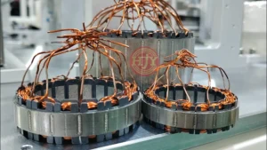
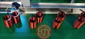
A systematic approach to stable mass production of internally wound stators.
In the mass production of brushless motor stators, needle winding machines perform winding, direction changes, and crossover movements directly inside the stator slots. This process is suitable for a wide range of internally wound stator products.
In practice, however, increasing machine speed can raise the risk of irregular wire arrangement, slot-position errors, enamel damage, and wire breakage. Reducing speed to protect winding accuracy may limit cycle time and overall output.
The production capability of a needle winding machine should therefore not be evaluated only by its maximum winding speed. Winding accuracy, tension stability, motion path, auxiliary time, changeover efficiency, yield, and long-term operating stability must all be considered.
Achieving both accuracy and efficiency requires systematic optimization of the hardware, process control, automation design, and production maintenance.
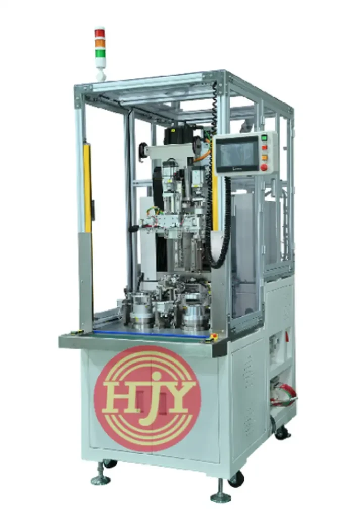
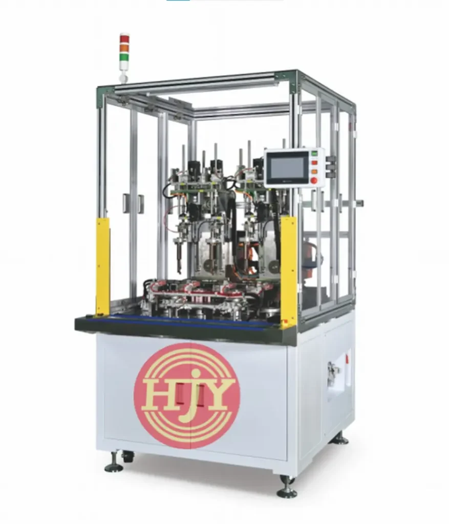
1. Hardware Provides the Foundation for Fast and Stable Winding
The hardware configuration of a needle winding machine determines its speed potential, positioning capability, and long-term stability. It also defines the available scope for process optimization.
1.1 High-Response Servo and Precision Transmission System
Needle winding involves needle movement, stator indexing, wire-path control, and coordinated multi-axis motion. Each motion axis must respond consistently during frequent starts, stops, direction changes, acceleration, and deceleration.
Depending on the product structure and equipment requirements, a bus-based motion-control architecture can be combined with servo motors, precision ball screws, timing belts, linear guides, bearings, and other transmission components to support:
- Needle motion-path control
- Stator indexing and positioning
- Needle entry and exit positioning
- Crossover path control
- Coordinated multi-axis motion
Servo and transmission components should be selected according to the stator dimensions, slot geometry, wire diameter, winding speed, and target cycle time. Appropriate mechanical rigidity and transmission accuracy help reduce vibration, positional deviation, and long-term accuracy variation during high-speed operation.
1.2 Multi-Stage Tension Control
During high-speed winding, magnet wire passes through different operating states, including feeding, slot entry, winding, direction reversal, crossover movement, and wire finishing. Each stage may require a different tension setting.
Excessive tension may stretch the wire, alter its diameter, or damage the enamel insulation. Insufficient tension may cause loose turns, unstable wire placement, and winding-dimension variation.
Tension sensors, active wire-feeding mechanisms, or servo tension systems can be used to assign suitable parameters to different stages and maintain stable wire behavior during acceleration, normal winding, direction reversal, and finishing.
The tension solution should be defined according to the wire diameter, wire stiffness, enamel characteristics, winding structure, and target speed.
2. Optimizing Cycle Time Through Process and Motion Control
Hardware provides machine capability, while the winding process and motion program determine whether that capability can be converted into stable output.
2.1 Optimize the Winding Path and Reduce Non-Productive Motion
The production time for one stator includes more than the winding operation itself. Needle entry, needle exit, crossover movement, indexing, direction changes, and axis return also contribute to the complete cycle time.
Provided that the needle does not contact the stator slot opening, insulator, or winding, motion-path optimization can be used to:
- Shorten crossover travel
- Reduce unnecessary waiting
- Optimize needle entry and exit paths
- Set suitable acceleration and deceleration curves
- Optimize the return sequence after winding
Path optimization should not focus only on the shortest travel distance. Sufficient clearance must be retained for wire bending, needle avoidance, and mechanical stability.
2.2 Improve Multi-Axis Coordination
High-speed winding places greater demands on the synchronization of the needle axis, stator indexing axis, and other motion axes.
Bus-based motion control, together with electronic cam, electronic gearing, or multi-axis interpolation functions, can coordinate position, speed, and timing so that needle movement remains synchronized with stator indexing.
Key factors in multi-axis control include:
- Stator indexing position
- Needle entry angle
- Direction-change position
- Crossover path
- Axis start and stop sequence
- Following error at high speed
The practical operating speed should be established gradually through sample trials and optimized according to winding quality and machine condition.
2.3 Set Speed Profiles According to the Wire and Product Structure
For needle winding, a higher speed is not always better. Wire diameter, stiffness, enamel abrasion resistance, slot geometry, slot-opening size, turn count, and winding structure all affect the achievable production speed.
For example:
- Thick or relatively rigid wire generally requires smoother acceleration and deceleration
- Fine wire requires careful control of tension variation and transient impact
- Products with narrow slot openings require sufficient positioning allowance for needle entry and exit
- High slot-fill windings require careful control of wire placement and force during the later winding stages
During commissioning, speed, acceleration, and tension parameters should be assigned to each winding stage. A suitable cycle time can then be determined while ensuring that the enamel, wire arrangement, and winding dimensions meet the acceptance criteria.
3. Reducing Auxiliary Time to Increase Effective Output
The efficiency of a needle winding machine should not be assessed only by pure winding time. Loading, unloading, indexing, lead-wire handling, axis return, inspection, and changeover also contribute to the complete production cycle.
3.1 Integrate the Necessary Automation Functions
Depending on the product structure and production requirements, a needle winding machine may be configured with:
- Automatic loading and unloading
- Automatic stator indexing
- Automatic start-wire and finish-wire handling
- Automatic wire hooking or lead-wire handling
- Wire-break or missing-wire detection
- Turn-count monitoring
- Abnormal-tension detection
- Multi-product recipe storage
- Interfaces to upstream and downstream automation
The automation level should be selected according to target capacity, product consistency requirements, and investment planning. The objective is not to add every possible function, but to reduce frequent manual operations and production waiting time.
3.2 Optimize Axis Return and Process Handover
Axis return, product unloading, and loading of the next part all affect the complete machine cycle.
Optimizing the axis return sequence, robot motions, and station handover can reduce non-processing time. Where safety conditions permit, selected actions may also be planned in parallel to shorten the overall cycle.
3.3 Improve Changeover Efficiency
For manufacturers producing several stator models, changeover time is an important factor in equipment utilization.
Replaceable fixtures, standardized needle assemblies, recipe management, and parameter recall can reduce repeated setup work. After changeover, the needle position, winding path, tension, and first-piece quality must still be verified before mass production begins.
4. In-Line Monitoring and Standardized Maintenance Support Long-Term Stability
Fast and accurate operation depends not only on initial commissioning, but also on the machine’s ability to maintain its condition during long-term production.
4.1 Monitor Critical Operating Parameters
Depending on the equipment configuration and project requirements, the system may monitor:
- Servo operating status
- Tension variation
- Wire-break or missing-wire status
- Equipment alarm records
- Production quantity
- Product model and recipe version
- Operating time of critical stations
- Electrical or vision-inspection results
When an abnormal condition occurs, the equipment can trigger an alarm, pause, or protective stop according to the predefined logic, preventing continued production under an abnormal state.
For projects requiring quality traceability, winding parameters and inspection results can also be linked to the product batch or barcode and exchanged with the customer’s MES.
4.2 Customize the Machine to the Product
Stators vary in slot count, slot geometry, inner diameter, stack height, wire diameter, and winding structure. These differences affect the needle design, motion travel, indexing method, and tension range required by the machine.
The following information should therefore be provided during equipment evaluation:
- Stator 2D and 3D drawings
- Slot opening and insulation structure
- Magnet-wire specification
- Turn count and winding direction
- Start-wire, finish-wire, and crossover routing
- Winding appearance and dimensional requirements
- Target cycle time and capacity
- Inspection and traceability requirements
After the product structure and process conditions are confirmed, the number of machine axes, fixture design, tension solution, and automation configuration can be selected to balance production efficiency and process stability.
4.3 Establish Standardized Operation and Maintenance Procedures
Operators should understand product changeover, parameter recall, first-piece confirmation, abnormal-condition handling, and daily inspection procedures.
Standardized operating procedures and regular inspection of the needle, fixtures, wire-guiding mechanism, transmission components, and tension system help reduce accuracy variation and downtime caused by wear, looseness, or incorrect parameter adjustment.
5. A Needle Winding Machine Should Not Be Evaluated by Maximum Speed Alone
Stable mass-production capability should be assessed using a combination of the following indicators:
- Complete cycle time per part
- Yield during continuous production
- Winding arrangement consistency
- Enamel damage and wire-break conditions
- Stator indexing and slot-position accuracy
- Changeover time
- Equipment failure rate and downtime
- Accuracy stability after extended operation
Effective production capacity is achieved only when a stable cycle time is maintained while the winding meets the required quality standard.
JHY Needle Winding Automation Solutions
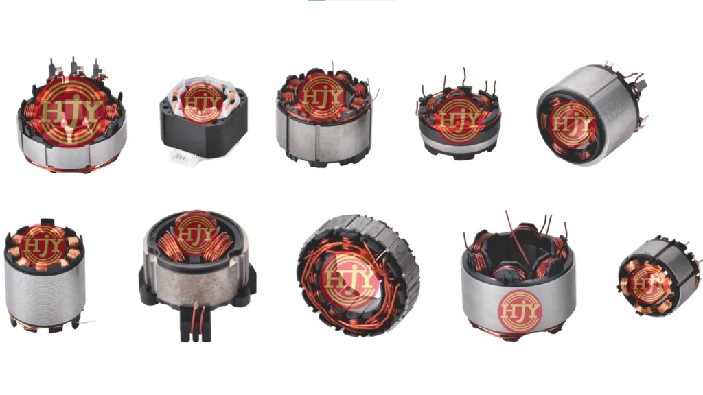
JHY provides needle winding equipment and automated production solutions based on the stator slot geometry, wire diameter, turn count, winding path, and target capacity.
Depending on the project, the solution may integrate precision winding, tension control, automatic loading and unloading, lead-wire handling, in-line inspection, data traceability, and interfaces to upstream and downstream processes.
From sample winding and process verification to mass production, the JHY engineering team evaluates the winding path, needle design, equipment configuration, and production cycle according to the customer’s drawings, samples, and quality requirements, helping establish a stable and repeatable stator winding process.
If you are evaluating a needle winding machine or stator winding automation project, send JHY your product drawings, winding parameters, samples, and target capacity. We will develop an equipment solution based on the actual product requirements.