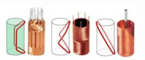
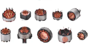
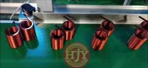
Flyer winding machines are widely used for automated external winding of motor stators. Depending on the product structure, they can be applied to brushless motors, outer-rotor motors, fan and pump motors, in-wheel motors, drone motors, and other externally wound stator products.
During external stator winding, the winding path, wire placement, tension, stator positioning, and lead-wire handling all affect coil geometry, winding dimensions, and production consistency. If flyer rotation, traverse movement, and tension control are not properly coordinated, wire displacement, overlapping turns, loose winding, enamel damage, or coil-dimension variation may occur.
The production capability of a flyer winding machine should therefore not be evaluated only by its maximum rotational speed. Winding quality, complete cycle time, product yield, changeover efficiency, and long-term operating stability must also be considered.
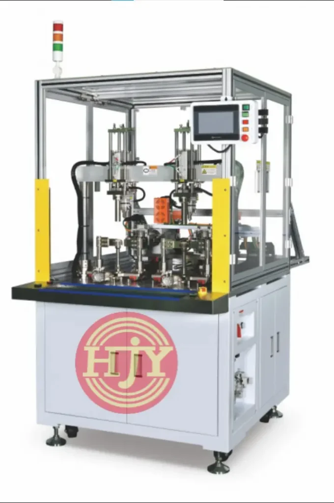
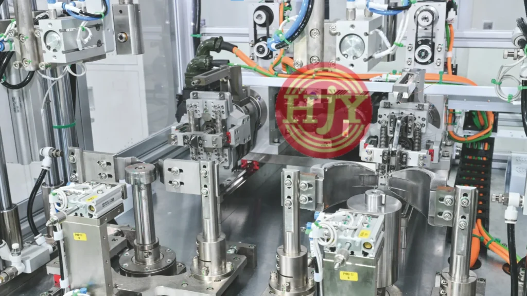
1. What Is a Flyer Winding Machine?
A flyer winding machine rotates a flyer mechanism around the stator or winding fixture to place magnet wire around the stator tooth, insulating bobbin, or specified winding path.
During production, the flyer axis, traverse axis, stator indexing axis, and auxiliary mechanisms operate according to a programmed sequence to complete:
- Start-wire positioning
- Flyer rotation and winding
- Axial or radial wire placement
- Stator indexing
- Crossover routing between teeth
- Finish-wire and lead-wire handling
Depending on the product structure, the machine can be designed with one, two, or multiple winding stations and integrated with automatic loading, taping, inspection, and downstream assembly processes.
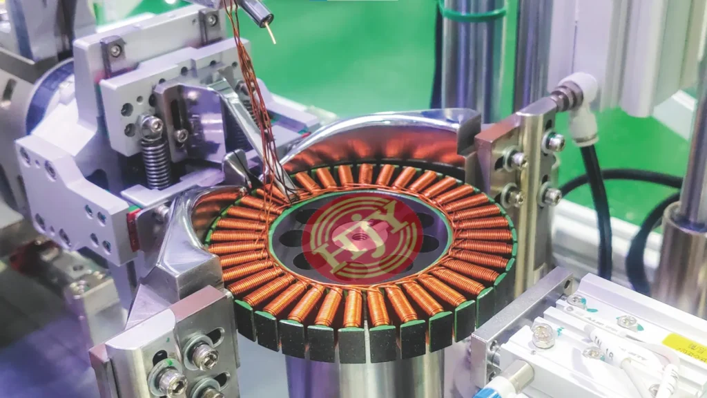
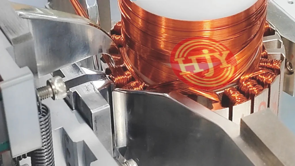
2. Main Machine Structure and Operating Principle
A complete flyer winding system normally includes a flyer drive, traverse mechanism, tension-control system, stator positioning fixture, indexing mechanism, and machine-control system.
2.1 Flyer Rotation Mechanism
The flyer mechanism drives the wire guide around the stator tooth or winding bobbin, placing magnet wire according to the programmed winding direction and turn count.
The mechanism requires sufficient rigidity and dynamic balance to reduce vibration and positional variation during high-speed rotation. The practical speed should be selected according to stator dimensions, wire diameter, wire stiffness, winding structure, and coil-shape requirements.
For thick wire, flat wire, or wire with high bending stiffness, the flyer torque, wire-guide design, minimum bending radius, and acceleration and deceleration profiles require particular attention.
2.2 Servo Traverse Mechanism
The traverse mechanism moves in coordination with flyer rotation and the product winding parameters, controlling the wire landing position and traverse pitch within the winding area.
For products requiring layered wire placement, the traverse path can be programmed according to the wire diameter, coil width, and number of layers.
The actual winding arrangement is also affected by:
- Magnet-wire diameter and tolerance
- Wire stiffness and surface condition
- Available winding-space dimensions
- Insulating bobbin structure
- Tension stability
- Flyer speed
- Traverse pitch
- Actual position of the previous layer
Whether strict layer-by-layer precision winding can be achieved must be verified using the product drawings and representative samples.
2.3 Tension-Control System
Magnet wire experiences different tension conditions during pay-off, acceleration, normal winding, deceleration, and direction changes.
Excessive tension may stretch the wire, damage the enamel, or alter the coil dimensions. Insufficient tension may result in loose turns, coil collapse, or unstable wire placement.
Depending on the wire diameter and winding speed, the machine can use magnetic, electronic, or servo tensioners, or an active wire-feeding mechanism. Different tension settings can be assigned to the individual winding stages.
High-speed applications, thick-wire products, or projects with strict coil-shape consistency requirements may also use tension monitoring and multi-stage tension control.
2.4 Stator Positioning and Indexing Mechanism
Stator positioning accuracy directly affects the wire landing point, winding position, and tooth-to-tooth consistency.
The fixture should be designed according to the stator inner and outer diameters, datum surface, slot geometry, and insulation structure, while keeping the product stable during flyer rotation.
For multi-tooth stators, the indexing mechanism rotates the stator according to the winding pattern and remains coordinated with the flyer, traverse, and crossover motions.
2.5 Machine-Control System
The control system manages flyer speed, traverse position, indexing angle, turn count, tension parameters, and the sequence of all machine mechanisms.
Through the HMI, operators can set or recall product recipes including:
- Winding direction
- Turn count
- Flyer speed
- Acceleration and deceleration profiles
- Traverse stroke and pitch
- Tension parameters
- Indexing angle
- Start-wire, finish-wire, and crossover paths
The feasibility and duration of product changeover must be evaluated according to stator dimensions, fixture structure, wire-diameter range, and winding path.
3. Key Factors Affecting Flyer Winding Quality
Flyer winding quality is not determined by one component alone. It results from the combined effects of motion control, wire characteristics, mechanical design, and process parameters.
3.1 Synchronization of Flyer and Traverse Motions
Flyer rotation and traverse movement must maintain a stable speed and positional relationship. If the traverse speed does not match the flyer rotation, wire accumulation, excessive spacing, or wire-placement deviation may occur.
Servo drives and bus-based motion control can manage the flyer, traverse, indexing, and other motion axes together and adjust the winding path and sequence to the product requirements.
3.2 Wire-Tension Stability
Tension variation directly affects winding tightness and the wire landing point. Transient tension impact should be controlled, particularly during starting, stopping, direction changes, and high-speed winding.
During commissioning, speed and tension parameters should be assigned to the individual winding stages instead of applying one setting throughout the entire cycle.
3.3 Wire Guide and Wire-Contact Components
The wire guide, guide pulleys, and other wire-contact parts should have smooth surfaces, with suitable bore sizes and guiding angles selected according to the wire diameter and characteristics.
Depending on the project, ceramic, carbide, or polished wire-contact components may be used to reduce friction and the risk of enamel damage.
Wire guides are wear parts and should be included in routine inspection and replacement plans.
3.4 Consistency of Stators and Insulators
Stator dimensions, insulating-bobbin position, and slot-opening conditions also affect winding performance. If incoming-part dimensions vary significantly, the wire landing point and coil geometry may change even when the machine parameters remain unchanged.
During project evaluation and commissioning, the incoming standards for stators, insulators, and magnet wire should be defined, and representative qualified samples should be used for continuous winding trials.
4. Main Functional Configurations
Depending on the product structure and required automation level, a flyer winding machine may be configured with:
- Single-, dual-, or multi-station winding
- Automatic loading and unloading
- Automatic stator positioning and indexing
- Automatic start-wire and finish-wire handling
- Crossover-wire control between teeth
- Single-wire or multi-wire parallel winding
- Multi-stage tension control
- Wire-break or missing-wire detection
- Turn-count monitoring
- Automatic wire cutting
- Product-recipe storage
- Barcode identification and data traceability
- MES and upstream or downstream process interfaces
The final configuration should be determined according to the stator dimensions, slot count, wire diameter, turn count, winding structure, target cycle time, and inspection requirements.
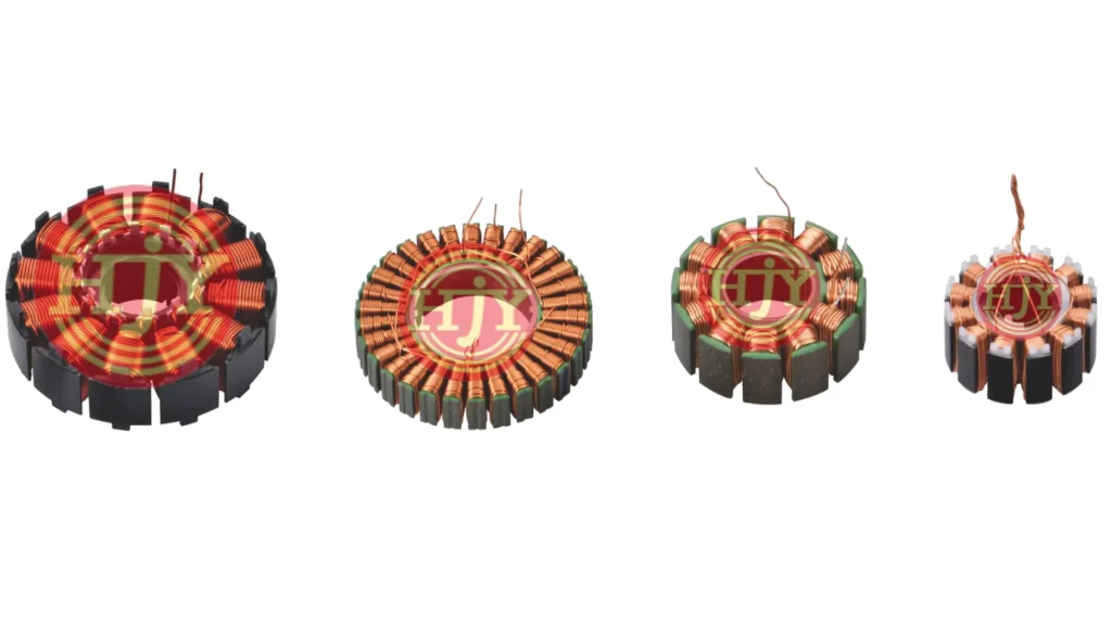
5. Main Advantages of Flyer Winding Machines
5.1 Suitable for Different External Stator Structures
Customized winding fixtures, wire guides, and motion programs allow the equipment to accommodate externally wound stators with different dimensions, slot counts, and winding structures.
5.2 Supports High-Speed Continuous Winding
The rotating flyer structure can achieve relatively high winding speeds when permitted by the product and process conditions.
Actual production capacity should be calculated using the complete cycle time, including loading, positioning, winding, indexing, wire cutting, and unloading, rather than the maximum flyer speed alone.
5.3 Helps Improve Batch Consistency
Products with similar structures may be changed over by replacing fixtures and wire guides and recalling the corresponding process recipe.
The compatible product range and actual changeover time must be evaluated according to the structural differences between models.
5.5 Suitable for Production-Line Integration
Flyer winding equipment can be combined with stator loading, insulator assembly, lead-wire handling, electrical testing, vision inspection, and finished-product unloading to form an automated production cell or complete line.
6. Maximum Flyer Speed Is Not the Only Evaluation Criterion
When evaluating flyer winding equipment, the following indicators should be considered:
- Complete production cycle time
- Yield during continuous production
- Winding-shape consistency
- Turn-count accuracy
- Wire-placement and crossover quality
- Enamel damage and wire-break conditions
- Tension stability
- Changeover time
- Service life of wear parts
- Long-term operating stability
- Automation and data-traceability capabilities
Effective mass-production capacity is achieved only when the equipment maintains a stable cycle while meeting the required winding-quality standard.
7. Information Required for Flyer Winding Project Evaluation
To evaluate the machine structure, winding process, automation configuration, and production cycle accurately, we recommend providing:
- Stator 2D and 3D drawings
- Stator and insulator samples
- Magnet-wire specification and material
- Turn count and winding direction
- Number of coil layers and wire-placement requirements
- Start-wire, finish-wire, and crossover paths
- Lead-wire length and position requirements
- Winding appearance and dimensional standards
- Product quality-inspection standards
- Target cycle time and annual capacity
- Product models to be accommodated
- Loading, unloading, and line-interface requirements
- Data-traceability and MES requirements
For high slot-fill, thick-wire, multi-wire parallel winding, or special-wire products, sample winding and process verification are recommended before finalizing the equipment solution.
JHY Flyer Winding Automation Solutions
JHY provides flyer winding equipment and automation solutions according to the stator dimensions, slot geometry, wire diameter, turn count, winding path, and target capacity.
Depending on the project, the solution may include single-, dual-, or multi-station winding, tension control, automatic loading and unloading, stator indexing, lead-wire handling, in-line inspection, data traceability, and interfaces to upstream and downstream processes.
From sample winding and small-batch validation to mass production, the JHY engineering team evaluates the flyer structure, traverse path, tooling solution, tension configuration, and production cycle using the customer’s drawings, samples, and quality requirements.
If you are evaluating a flyer winding machine or external stator winding automation project, send JHY your product drawings, winding parameters, samples, and target capacity.