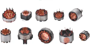
As vehicle electrification and intelligent control continue to advance, braking systems, transmission controls, thermal-management systems, electric drive systems, and chassis actuators place higher demands on the response, operating stability, and service life of solenoid valves and electromagnetic actuators.
As a critical component of these devices, the coil’s turn count, winding structure, tension condition, resistance consistency, and insulation reliability can affect electromagnetic output and batch-to-batch consistency.
Some automotive electromagnetic coils use fine magnet wire, high turn counts, and multilayer winding structures. Their production can be affected by tension variation, wire damage, accumulated traverse errors, and differences in manual operation. Establishing a stable, repeatable, and traceable precision-coil process is therefore an important requirement for automotive electromagnetic component manufacturing.
1. Main Manufacturing Challenges of Automotive Precision Coils
Automotive solenoid-valve and actuator coils vary significantly in structure, wire diameter, turn count, and electrical parameters. Their automated production commonly needs to address the following challenges.
1.1 Fine-Wire Breakage and Enamel-Damage Risks
Some precision electromagnetic coils use fine magnet wire. During pay-off, guiding, acceleration, winding, and finishing, the wire can be affected by transient tension, friction, and mechanical impact.
Excessive tension may stretch the wire, alter its diameter, damage the enamel, or cause breakage. Insufficient tension may lead to loose turns, unstable wire placement, and variation in coil geometry.
1.2 Accumulated Errors in Multilayer Winding
For coils with high turn counts, the actual position of one layer affects the placement of the next. If traverse pitch, winding position, or tension control is unstable, the error can accumulate as the number of layers increases.
This may result in overlapping turns, skipped positions, local wire buildup, excessive coil height, or inconsistent winding geometry.
1.3 Electrical-Parameter Consistency
Coil resistance is influenced by wire diameter, effective wire length, turn count, wire temperature, and measurement conditions. Inductance is also affected by the magnetic core, air gap, assembly condition, and test frequency.
Improving batch consistency therefore requires not only controlled turn count and wire placement, but also consistent incoming-material standards, process parameters, and test conditions.
1.4 Lead-Wire Processing and Terminal Connection
Start-wire and finish-wire handling, enamel removal, terminal wrapping, welding, and soldering can introduce wire breakage, incomplete connections, residual enamel, and terminal-position variation, particularly on fine-wire products.
Depending on the product, mechanical, thermal, or laser stripping, direct soldering, or another connection process may be used. The selected method should be verified according to the wire diameter, enamel type, and terminal structure.
1.5 Traceability Requirements for Automotive Products
Automotive component production typically emphasizes process records, batch management, and exception traceability. Coil production equipment may therefore need to record critical process parameters and inspection results in addition to completing the winding process.
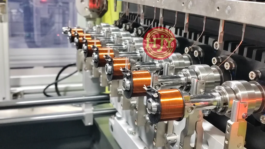
2. JHY Precision Electromagnetic Coil Automation Solution
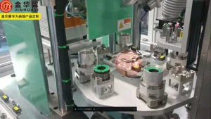
For solenoid valves, actuators, and other automotive electromagnetic coils, JHY can configure precision winding, tension control, lead-wire processing, taping, loading and unloading, inspection, and data traceability according to the product structure.
The process and automation level should be determined by the wire diameter, turn count, bobbin structure, terminal design, and target capacity.
2.1 Precision Wire Placement and Motion Control
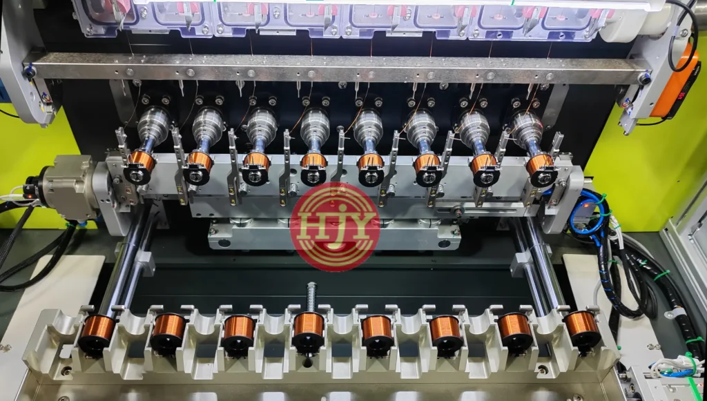
The winding system controls spindle speed, turn count, traverse stroke, traverse pitch, acceleration, and deceleration according to the product program.
For multilayer products, the traverse path can be planned according to the wire diameter, coil width, and number of layers. Servo motion control coordinates the positional relationship between the spindle and traverse axes.
Precision wire placement is also affected by:
- Magnet-wire diameter and tolerance
- Dimensions of the bobbin winding area
- Wire stiffness and surface condition
- Tension stability
- Traverse pitch
- Winding speed
- Actual position of the preceding layer
For products with many layers or demanding placement requirements, sample winding is recommended to confirm process feasibility.
2.2 Multi-Stage Tension Control
The required tension may differ during start-up, acceleration, normal winding, direction reversal, deceleration, and finishing.
Depending on the project, the equipment can use magnetic, electronic, or servo tensioners, or an active wire-feeding mechanism, with corresponding parameters assigned to each winding stage.
Tension monitoring, wire-break detection, and abnormal-condition alarms can also be added to help reduce the risk of fine-wire breakage, loose winding, and dimensional variation.
2.3 Lead-Wire and Enamel-Stripping Processes
Depending on the product structure, the equipment may be configured with:
- Automatic start-wire and finish-wire handling
- Lead-wire length control
- Terminal hooking or wrapping
- Mechanical enamel stripping
- Thermal enamel stripping
- Laser enamel stripping
- Automatic soldering or welding
- Continuity and resistance testing
The stripping and connection process should be selected according to the wire diameter, enamel material, terminal structure, and customer quality standard. Ultra-fine wire and special-enamel products should be validated using samples before the final process is selected.
2.4 Automatic Taping and Insulation Processing
An automatic taping unit can be configured for coils requiring tape fixation or insulation protection.
The system can control tape pay-off, tension, wrap count, overlap ratio, and cutting to help maintain consistent tape position and wrapping condition.
The tape type, width, wrapping direction, and number of wraps should be determined according to the product drawing and insulation requirements.
2.5 Automatic Loading, Unloading, and Process Transfer
Depending on the bobbin structure and incoming-material format, loading and unloading can use a vibratory bowl, linear feeder, tray, conveyor, or robot.
Not every bobbin is suitable for vibratory-bowl feeding. Products with long terminals, easily deformed structures, or damage-sensitive surfaces may be better handled with trays or dedicated transfer mechanisms.
Automated transfer can reduce repeated manual loading and minimize production variation caused by inconsistent orientation or positioning.
3. In-Line Inspection and Production Traceability
To strengthen quality control during mass production, in-line inspection functions can be integrated according to project requirements.
3.1 Electrical Testing
Optional test items include:
- Coil resistance
- Surge or interturn testing
- Insulation resistance
- Hipot testing
- Continuity and short-circuit detection
- Inductance testing
Wire-temperature acquisition and temperature compensation can be added to resistance testing when required.
Inductance results are also affected by the magnetic core, assembly condition, test frequency, and instrument settings. Customers should therefore provide clear test conditions and acceptance criteria.
3.2 Vision Inspection
A CCD vision system may inspect:
- Wire placement and coil appearance
- Start-wire and finish-wire positions
- Lead-wire length
- Tape position
- Terminal or joint appearance
- Part orientation
- Missing or incorrectly assembled components
Vision-inspection capability depends on the defect characteristics, imaging angle, lighting conditions, and customer acceptance criteria. Accepted samples, rejected samples, and representative defect samples are recommended during project evaluation.
3.3 Data Traceability
Production data can be linked to a barcode, QR code, or batch number, including:
- Product model and batch
- Winding turn count
- Winding-program version
- Tension parameters
- Taping parameters
- Electrical test results
- Vision-inspection results
- Equipment alarm records
- Production time
- OK or NOK status
MES or production-management-system interfaces can also be reserved according to the customer’s digital-manufacturing requirements.
4. Customer Value of the Automation Solution
4.1 Improved Batch Consistency
Program-controlled winding, tension management, standardized tooling, and inspection processes reduce manual variation and help maintain consistent turn counts, coil geometry, and electrical parameters.
4.2 Reduced Fine-Wire Production Risk
Appropriate wire-guiding structures, tension parameters, and motion profiles help reduce the risk of stretching, breakage, and enamel damage during high-speed fine-wire winding.
4.3 Reduced Manual Operation
Automatic loading, winding, taping, inspection, and sorting can reduce repetitive manual work and process waiting time.
4.4 Support for Multi-Model Production
Modular tooling and recipe management can support changeover between products with similar structures. The compatible product range and actual changeover time should be evaluated according to the differences between products.
4.5 Stronger Quality Traceability
Linking process parameters and inspection results to a batch or unique product code provides data for quality analysis, exception tracking, and production management.
5. Precision-Coil Automation Should Not Be Evaluated by One Parameter Alone
Mass-production capability cannot be determined only by maximum speed, number of winding layers, or a single inspection-accuracy figure. It should be evaluated using:
- Complete production cycle time
- Yield during continuous production
- Fine-wire breakage conditions
- Wire-placement and coil-geometry consistency
- Resistance and inductance test conditions
- Taping and lead-wire processing quality
- Changeover time
- Service life of wear parts
- Long-term operating stability
- Data recording and traceability capability
Resistance, inductance, and product durability are not determined by the winding equipment alone. They are also affected by the wire, magnetic core, bobbin, assembly, and test conditions. Final performance targets should be confirmed through sample testing and continuous-production validation.
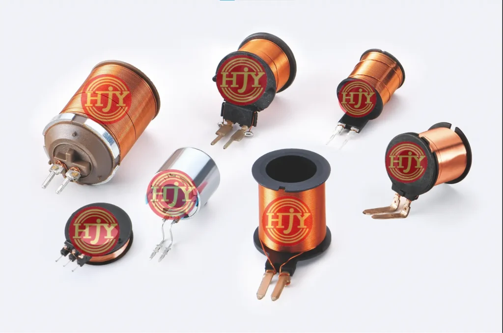
6. Applicable Products and Applications
JHY precision-coil automation solutions can be applied to:
- Automotive solenoid-valve coils
- Braking-system electromagnetic coils
- Transmission-control coils
- Thermal-management solenoid valves
- Electromagnetic actuator coils
- Relay coils
- Sensor coils
- Other fine-wire, high-turn-count precision coils
Winding, stripping, taping, and connection processes vary significantly between products. The equipment solution should therefore be customized to the specific application.
7. Information Required for Project Evaluation
To evaluate the winding process, automation configuration, production cycle, and quotation accurately, we recommend providing:
- Coil-assembly 2D and 3D drawings
- Bobbin and terminal drawings
- Bobbin and coil samples
- Magnet-wire specification and enamel type
- Turn count, layer count, and wire-placement requirements
- Start-wire and finish-wire paths
- Lead-wire length and position
- Enamel-stripping and terminal-connection method
- Tape specification and wrapping requirements
- Resistance, inductance, and insulation standards
- Appearance and dimensional acceptance criteria
- Target cycle time and annual capacity
- Product models to be accommodated
- Loading and unloading method
- Barcode, MES, and data-traceability requirements
For ultra-fine wire, densely wound multilayer coils, or special-enamel products, sample winding and process validation are recommended before the equipment solution is finalized.
JHY Automotive Precision Electromagnetic Coil Automation Solutions
JHY provides precision-coil manufacturing solutions ranging from standalone equipment to automated production cells according to the wire diameter, turn count, bobbin structure, winding dimensions, lead-wire method, and target capacity.
Depending on the project, the solution may integrate precision wire placement, tension control, lead-wire processing, enamel stripping, taping, automatic loading and unloading, electrical testing, vision inspection, and data traceability.
From sample winding and small-batch validation to mass production, the JHY engineering team evaluates the winding process, tension solution, equipment configuration, and production cycle using the customer’s drawings, samples, and quality standards. The resulting solution is configured for automotive solenoid valves, actuators, and other precision electromagnetic coils.
If you are planning an automotive electromagnetic coil or other precision-coil automation project, send JHY your product information, samples, and target capacity.