

Segmented stators provide open access to the winding area and create more flexibility for concentrated winding designs. Compared with winding a completely closed stator, the open structure can make it easier to handle thick wire, multiple wires in hand and demanding coil shapes. It can also support a higher slot fill and a shorter end winding when the stator and coil are designed appropriately.
However, segmented stator winding is not one fixed process.
The suitable winding method depends on the stator structure, the way the coils are electrically connected, the wire specification, the available winding space, the required coil dimensions and the subsequent stator assembly process. Depending on these conditions, the solution may use spindle winding, stacked winding, rolling winding, needle winding or flyer winding.
Selecting the equipment before understanding these product conditions can result in an unsuitable winding path, excessive crossover wiring, unstable coil dimensions or difficulties during stator closing and assembly. A reliable solution therefore starts with the product and process requirements—not with a standard machine configuration.
Why Are Segmented Stators Used?
In a segmented stator, the winding area is opened before the stator is assembled into its final circular form. This provides several potential manufacturing advantages:
- Better access to the winding area
- Greater flexibility for concentrated windings
- Easier handling of thick wire or multiple wires in hand
- More possibilities for controlling coil width and end-winding dimensions
- The possibility of winding individual teeth before final stator assembly
- More options for integrating winding, inspection, closing, welding and testing
These advantages do not occur automatically. The open structure also introduces several process challenges:
- Each segment or tooth must be positioned accurately during winding.
- Start wires, finish wires and crossover wires must be controlled.
- Coil width and height must remain within the space available after closing.
- Adjacent coils must not interfere when the stator is assembled.
- The winding direction and electrical connection must follow the winding diagram.
- The final roundness and segment position depend on the closing and assembly method.
For this reason, segmented stator winding should be evaluated together with the complete manufacturing sequence.
Two Fundamental Stator Structures
The first process decision is to identify whether the product uses completely individual segments or an expanded stator structure.
Individual Stator Segments
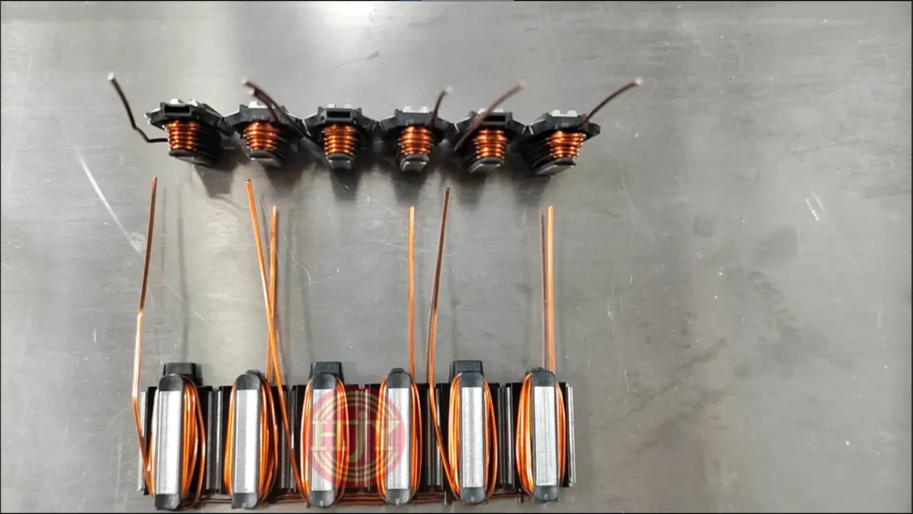
Each stator tooth is a separate component. The segments are wound first and then arranged and assembled into a circular stator.
The winding strategy can follow two main approaches:
- Independent winding: Each segment is wound and cut separately, creating an individual coil with its own start and finish leads.
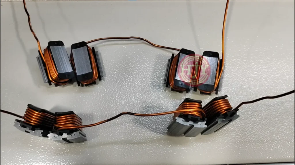
- Continuous multi-segment winding: One wire continuously winds two, three, four or more separate segments, with controlled crossover lengths between the coils.
Independent winding offers flexibility in segment handling and winding direction, but it normally requires more subsequent electrical connections. Continuous winding can reduce terminals, welding or manual connection work, but the crossover wires must be designed for the segment arrangement and final stator assembly.
Expanded Stators
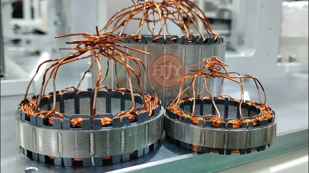
In an expanded stator, multiple stator teeth remain mechanically connected during winding. The core is held in a linear or open configuration so that the winding tool can access the teeth. After winding, the stator is formed into a circular shape and then closed, joined or welded according to the product design.
The connection between the teeth helps preserve their sequence, but the winding process must still control:
- The transfer of wire from one tooth to the next
- The winding direction of each coil
- Crossover-wire position and length
- Coil dimensions before the stator is closed
- Clearance between adjacent coils after closing
- Mechanical stress on the wire during forming
Winding Methods for Individual Stator Segments
Individual stator segments can be wound using different mechanisms and workpiece motion paths. The following methods do not describe interchangeable machines; each represents a different combination of product arrangement, wire path and mechanical movement.
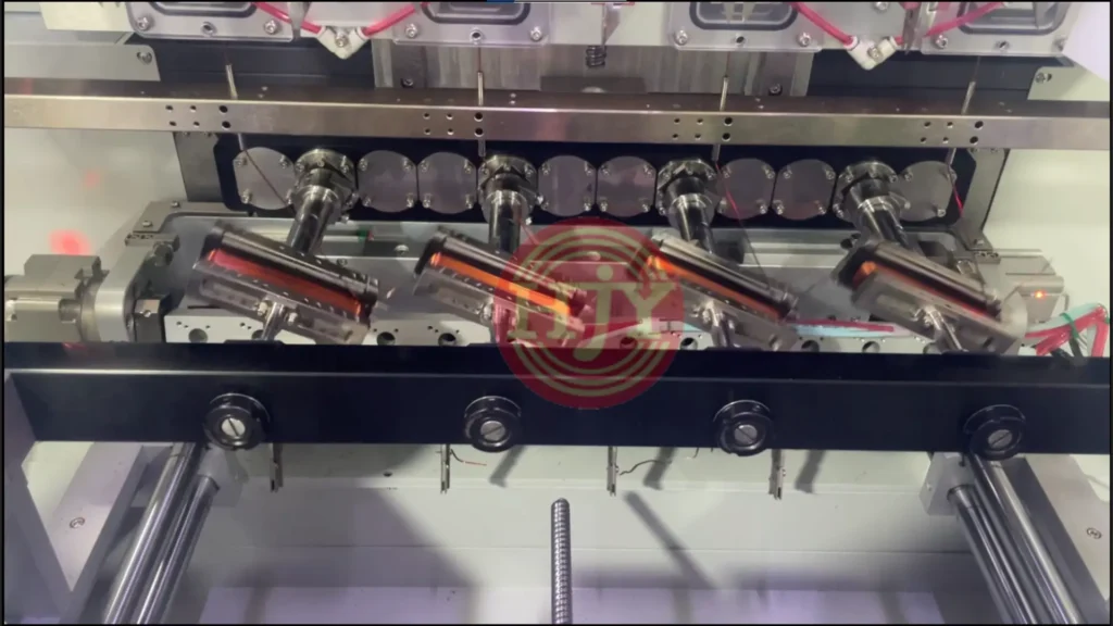
1. Individual Segment Spindle Winding
In spindle winding, one stator segment is mounted on a spindle. The spindle rotates the workpiece while a wire guide positions the wire across the winding area.
A machine can be configured with several spindles so that multiple segments are wound simultaneously. For example, a four-spindle machine can produce four separate wound segments during one winding cycle.
Typical characteristics include:
- One independent segment per spindle
- Independent start and finish leads for each coil
- Multi-spindle production for higher capacity
- Programmed spindle speed and wire-guide position
- Changeover through customized fixtures and winding programs
It is important to distinguish multi-spindle production from continuous multi-segment winding. Four spindles winding four separate coils at the same time do not constitute four-segment continuous winding. Continuous winding specifically means that one uninterrupted wire connects several segment coils.
2.Stacked Winding
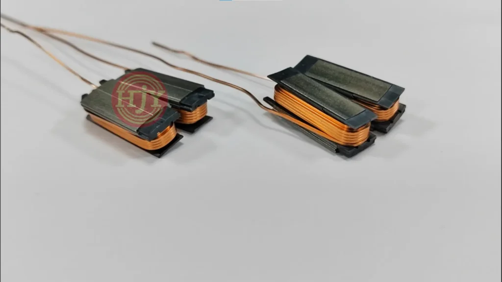
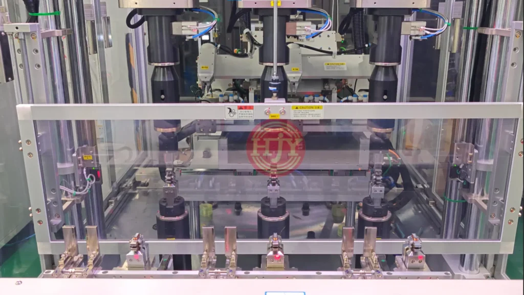
In stacked winding, several individual segments are positioned along the same winding axis. One wire can be guided from one segment to the next so that the segments are wound sequentially without cutting the wire between coils.
The segments are stacked for processing, but they remain separate components. The term “stacked winding” therefore describes the arrangement of the workpieces; it does not mean that the segments are mechanically connected or that several wires are stacked together.
Potential benefits include:
- Continuous winding of several separate segments
- Fewer subsequent electrical connection points
- Controlled crossover length between adjacent segment coils
- Compact tooling arrangement
- A defined sequence for grouped segment production
The engineering challenge is to transfer the wire between the stacked positions without damaging the insulation or losing control of the crossover path. The required crossover length must also match the final segment positions after assembly.
3.Rolling Winding
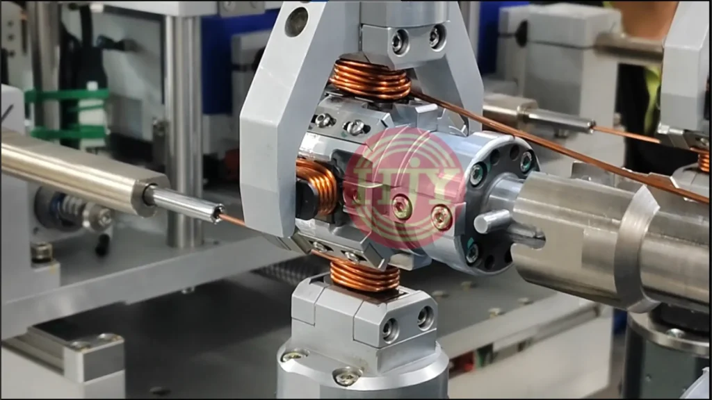
In rolling winding, individual segments are arranged on a rotary, multi-face or rolling fixture. The fixture turns, rolls or indexes to bring each segment through the winding path.
One wire can continuously wind several segments while the fixture controls the transition between them. Compared with a purely axial stacked arrangement, the rolling mechanism provides another way to manage workpiece orientation and wire transfer.This method can be considered when the product requires:
- Continuous winding of multiple independent segments
- Controlled orientation of each segment during winding
- A defined crossover path between segment coils
- Handling of relatively stiff or thick wire
- Reduced subsequent manual connection work
The feasibility depends on segment geometry, bending space, wire stiffness, number of connected segments and tooling clearance.
4.Needle Winding for Individual Segments
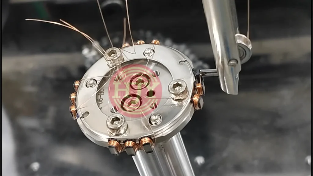
Needle winding can also be used for completely independent stator segments. A needle or nozzle carries the wire around the winding area while the fixture provides the required rotation, oscillation or indexing movement.
The segments may be loaded individually on a circular indexing fixture. After one segment is wound, the fixture indexes to the next segment and the same wire continues to form the next coil. This makes it possible to produce a continuously connected two-, three- or multi-segment group.
Needle winding offers flexibility in wire guidance, particularly when the process requires a controlled external path around each tooth. However, the available clearance for the needle and wire must be checked carefully against the segment geometry and coil build.
Winding Methods for Expanded Stators
Expanded stators can also be wound using different mechanisms. Needle winding and flyer winding are two important options, and even within needle winding the product can be arranged in different orientations.
1. Vertical Needle Winding
In vertical needle winding, the expanded stator is held in a vertical orientation. The needle moves through and around the winding area while the machine coordinates the required transverse movement at both ends of the tooth.
After one tooth is completed, the winding mechanism or fixture moves to the next tooth. The wire can remain continuous between teeth according to the winding diagram.
“Vertical winding” in this context describes the stator orientation and primary needle movement. It does not refer to edgewise winding of rectangular wire.
2. Horizontal Needle Winding
In horizontal needle winding, the expanded stator is placed flat on a fixture. The needle follows a reciprocating path around the tooth while the mechanism moves along the expanded core to complete the required sequence.
Vertical and horizontal needle winding share the same basic principle: the needle carries the wire along a controlled path around each tooth. Their main differences are:
- Stator orientation
- Fixture support
- Relative movement between the needle and tooth
- Available wire-guiding space
- Transfer path between adjacent teeth
The selection should be based on product geometry and process stability, rather than treating one orientation as universally better.
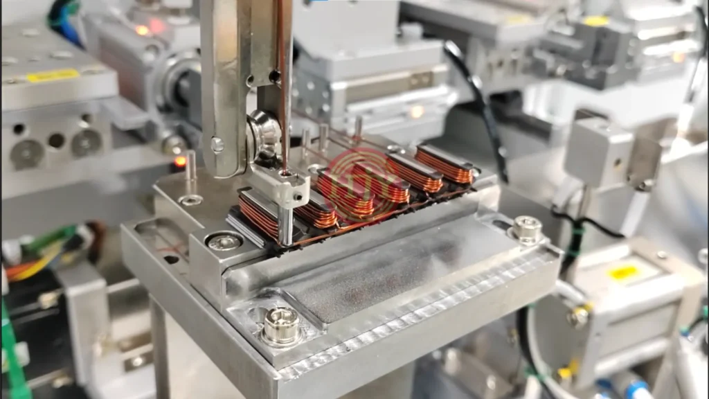
Flyer Winding for Expanded Stators
In flyer winding, the expanded stator tooth is accessible from the outside. A rotating flyer carries the wire around the tooth while the workpiece remains substantially stationary in the winding position.
The mechanism then transfers to the next tooth or the fixture indexes the product according to the required winding sequence.
Flyer winding can provide high winding speed when the tooth structure offers sufficient external space for the rotating flyer. Its feasibility depends on:
- Space around the tooth
- Wire diameter and stiffness
- Required coil width and height
- Flyer clearance
- Wire transfer between teeth
- Start and finish lead requirements
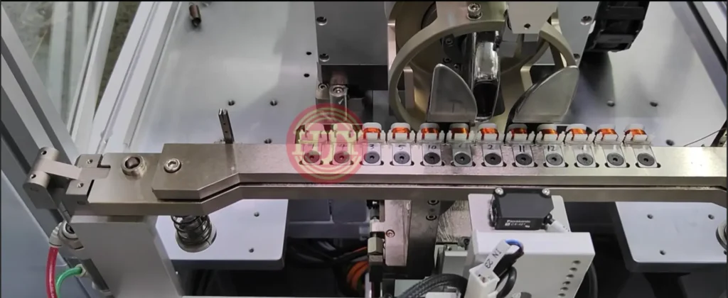
Comparison of the Main Winding Methods
| Winding method | Typical stator structure | Coil relationship | Main workpiece/tool motion | Key characteristic |
|---|---|---|---|---|
| Spindle winding | Individual segment | Normally independent | Segment rotates on spindle | Multi-spindle production possible |
| Stacked winding | Individual segments | Continuous winding possible | Segments arranged along one axis | Compact multi-segment wire transfer |
| Rolling winding | Individual segments | Continuous winding possible | Fixture rolls, turns and indexes | Flexible segment orientation during linking |
| Needle winding | Individual or expanded | Independent or continuous | Needle reciprocates; fixture coordinates movement | Controlled and flexible wire path |
| Flyer winding | Typically expanded/open teeth | Continuous winding possible | Flyer rotates around tooth | High-speed winding with sufficient clearance |
This table is a general process overview, not a final selection guide. A product drawing and winding specification are still required because two visually similar stators may require different equipment configurations.
Key Factors in Winding-Process Selection
Core Structure
The machine must first be designed around completely individual segments or a connected expanded core. This decision affects clamping, indexing, wire transfer and unloading.
Independent or Continuous Winding
The winding diagram must identify whether each segment requires separate leads or whether one wire should continuously connect several coils. The number of connected segments—such as two-, three- or four-segment winding—must also be confirmed.
Wire Specification
Required information includes:
- Conductor diameter or cross-section
- Insulation thickness
- Number of wires in hand
- Material and insulation type
- Minimum allowable bending radius
- Required winding tension
Thick wire and multiple wires in hand increase bending force and springback. They also affect the size of the guide mechanism, the available winding speed and the final coil shape.
Number of Turns and Winding Direction
The number of turns, winding direction and coil sequence must follow the electrical winding diagram. For continuous multi-segment winding, the relationship between winding direction and lead connection must be evaluated together.
Coil Dimensions
Coil width, coil height and end-winding dimensions must remain compatible with the final circular stator. A segment can appear acceptable immediately after winding but still create interference when positioned next to adjacent wound segments.
Slot fill alone should therefore not be used as the only quality target. The process must also control the final coil envelope.
Start, Finish and Crossover Wires
Lead-wire and crossover-wire positions influence:
- Segment unloading
- Segment handling
- Stator assembly
- Terminal connection
- Welding or soldering
- Electrical insulation and clearance
For continuous winding, the crossover length must be long enough for assembly but not so long that it creates uncontrolled loops or interference.
Production Capacity
The required cycle time and annual volume determine whether the machine should use:
- A single spindle or multiple spindles
- One winding station or several synchronized stations
- A circular indexing fixture
- Automatic loading and unloading
- Integrated inspection and downstream assembly
Higher automation should be selected according to stable process requirements, not added only for appearance.
Subsequent Stator Assembly
Winding and stator assembly are directly connected. The winding solution must consider how the product will be:
- Transferred after winding
- Arranged in the correct sequence
- Closed or assembled into a circular shape
- Clamped and positioned
- Welded or mechanically joined
- Electrically connected
- Inspected and testedThe optimum winding path may change when the downstream assembly method changes.
Coil-Shape and Process Control
A stable segmented stator winding process should control more than the number of turns. Important control targets include:
- Winding tension during different stages
- Wire position and distribution
- Coil width and height
- End-winding dimensions
- Crossover-wire location
- Start- and finish-wire consistency
- Insulation protection
- Repeatability between segments and stations
Tension may need to change between wire starting, normal winding, layer or position transition and wire finishing. The objective is not simply to apply the highest possible tension. Excessive tension can damage insulation, deform the wire or load the segment and fixture unnecessarily.
The achievable coil shape is also influenced by the wire diameter, number of turns, insulation system, segment geometry and slot fill. Equipment control is essential, but final results should be confirmed through sample winding and process validation.
From Winding to Stator Closing
Segmented stator quality cannot be evaluated only by inspecting an individual wound tooth.
After closing or assembly, the complete stator must meet requirements for:
- Overall diameter
- Roundness
- Segment position
- Coil clearance
- Crossover-wire routing
- Insulation distance
- Terminal position
- Electrical performance
Different closing strategies use different control principles. For example, one approach may control the final outer diameter through a cage-type fixture whose accuracy depends strongly on fixture machining. Another approach may clamp and position each segment individually, providing more direct control of the position of every stator piece.
The appropriate method depends on the required tolerance, process capability, tooling cost and production volume. Roundness or process-capability values should only be confirmed after the product structure, measurement method, fixture strategy and validation conditions have been defined.
A Practical Evaluation Process
Before developing a segmented stator winding solution, the following information should be reviewed:
- Stator and segment 2D/3D drawings
- Individual segment or expanded-core structure
- Winding diagram and phase connection
- Wire specification and number of wires in hand
- Number of turns and winding direction
- Independent or continuous multi-segment winding
- Required crossover lengths and lead positions
- Maximum coil width, height and end-winding dimensions
- Final stator-closing and joining method
- Cycle-time target and annual production volume
- Inspection, traceability and automation requirements
- Samples and trial wire for process validation
Based on this information, the winding mechanism, fixture concept, number of stations, tension-control configuration and downstream automation can be evaluated.
Customized Segmented Stator Winding Solutions
JHY develops customized winding equipment and automation solutions for individual stator segments and expanded stators. Depending on the product, the solution can include:
- Spindle, needle, flyer, stacked or rolling winding
- Single-wire or multi-wire winding
- Independent or continuous multi-segment winding
- Automatic wire clamping and cutting
- Controlled start, finish and crossover-wire handling
- Customized fixtures and changeover programs
- Automatic loading and unloading
- Vision or dimensional inspection
- Segment arrangement and stator closing
- Welding, electrical testing and traceability
Our objective is not simply to complete the winding operation. The process is developed around the relationship between:
Winding → Wire Management → Coil-Shape Control → Stator Assembly → Inspection
There is no single winding method suitable for every segmented stator. The right solution is a combination of stator structure, winding mechanism, workpiece movement, electrical connection and final assembly requirements.
Request a Process EvaluationAre you developing a new segmented stator or evaluating an automated winding process?
Send us your stator drawing, winding diagram, wire specification, coil requirements and production target. Our engineering team can evaluate the suitable winding path and automation configuration for your application.


