Explore the structural characteristics, manufacturing challenges and automated production methods of straight, skewed honeycomb and diamond windings for coreless motors.
Coreless motors use self-supporting, ironless, cup-shaped windings and are known for their low rotational inertia, fast dynamic response, smooth operation and high power density. They are widely used in precision drives, robotics, aerospace systems, medical devices and advanced industrial automation.
Unlike conventional iron-core motors, coreless motors do not use iron teeth or slots to support the winding. The enamelled wire must therefore be formed directly into a mechanically stable and dimensionally accurate cylindrical structure. Wire arrangement, winding tension, winding path, thermal bonding and forming accuracy can all directly affect motor performance and production consistency.
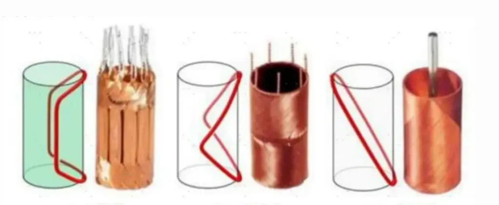
Common coreless motor windings include straight, skewed or honeycomb, and diamond winding configurations. Each structure has different characteristics in terms of copper fill, end-winding dimensions, structural uniformity, manufacturing complexity and automation requirements.
1. Three Common Coreless Motor Winding Structures
1.1 Straight Winding
In a straight winding, the main active conductor sections are arranged approximately parallel to the armature axis.
During production, self-bonding enamelled wire is wound to the specified number of turns and then arranged, rolled and formed into a cup-shaped winding. Thermal bonding, adhesive curing or another fixing process may be used to provide the required mechanical strength.
Key Characteristics
- Long active conductor sections and good utilisation of the available winding space
- Relatively straightforward winding geometry
- Potentially greater wall thickness in the central section
- Careful control is required to prevent wire overlap and uneven arrangement
- Additional space may be required for lead wires and end connections
- Subsequent forming is important for controlling roundness, wall thickness and overall uniformity
Straight windings are suitable for products that require a high proportion of active conductors and can accommodate subsequent forming and assembly processes.
1.2 Skewed Winding — Honeycomb Winding
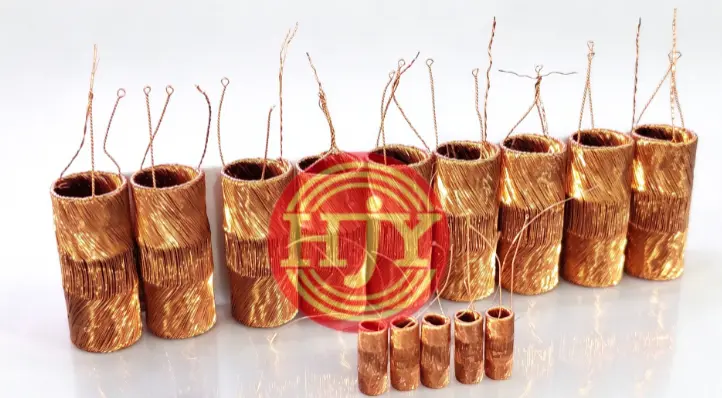
In a skewed or honeycomb winding, the enamelled wire is arranged at a defined angle to the armature axis. The conductors cross each other to form a self-supporting mesh or honeycomb structure.
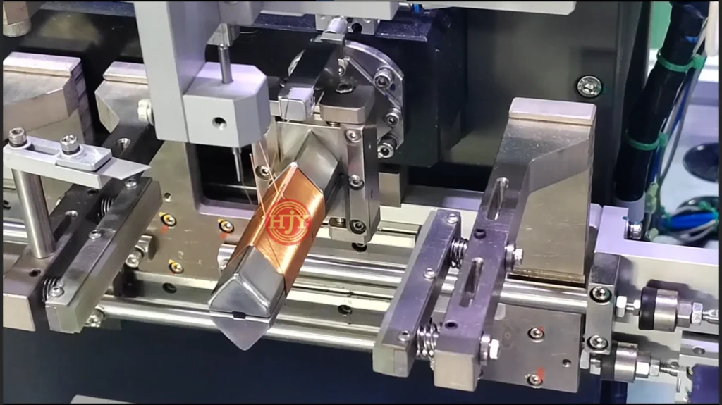
A typical process uses a dedicated winding mandrel equipped with positioning pins or other wire-guiding features. The mandrel diameter mainly defines the winding inner diameter, while the axial distance between the positioning features and the programmed winding path determine the winding length and end geometry.
The machine coordinates mandrel rotation with the axial reciprocating movement of the wire guide, allowing the wire to be wound continuously at a defined angle.
Key Characteristics
- The complete winding can be produced through a continuous winding process
- Compact end windings help reduce the axial length of the motor
- The crossed conductor arrangement forms a stable self-supporting structure
- Some layer overlap occurs at wire-crossing areas
- Copper fill depends on winding angle, wire diameter and conductor arrangement
- Accurate winding paths, tension control and mandrel positioning are essential
A honeycomb winding combines continuous winding with compact end geometry. However, its design must balance winding angle, copper utilisation and manufacturing stability.
1.3 Diamond Winding
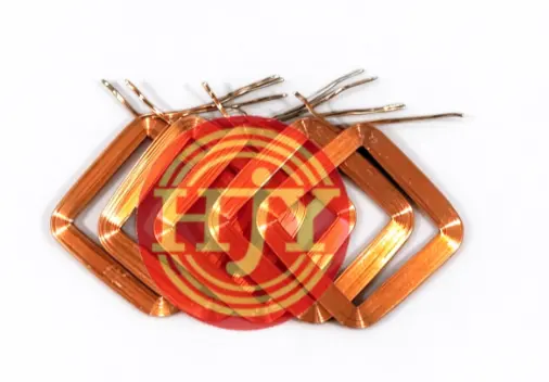
A diamond winding is normally produced from multiple preformed coil elements arranged at specified angles and phase positions to create a complete cylindrical winding.
Self-bonding enamelled wire is first wound on a dedicated tool to form an individual diamond or near-diamond-shaped coil. The coil elements then undergo preforming, shaping, positioning, initial cylindrical forming, thermal bonding and final sizing.
Key Characteristics
- Good control of individual coil geometry and winding angle
- Ordered conductor arrangement and uniform winding structure
- Consistent wall thickness, roundness and finished dimensions
- Production can use sequential single-coil winding or a multi-station automated system
- High accuracy is required during preforming, positioning and thermal bonding
- Equipment and tooling must be customised to the specific product design
Diamond windings are suitable for applications requiring high dimensional consistency and stable batch production. Actual production efficiency depends on the number of coil elements, winding cycle time, forming stages, bonding method and automation configuration.
2. Comparison of the Three Winding Structures
Comparison of Coreless Motor Winding Structures
| Comparison | Straight Winding | Skewed/Honeycomb Winding | Diamond Winding |
| Main structure | Active conductors are approximately parallel to the axis | Conductors cross at a defined angle | Multiple preformed coils are assembled |
| Typical forming method | Winding, arrangement, rolling and forming | Continuous cross-winding on a mandrel | Individual coil winding, arrangement and cylindrical forming |
| Copper utilisation | Relatively high | Affected by the crossing angle | High with an ordered arrangement |
| End-winding size | Relatively large | Compact | Controllable through coil design |
| Structural uniformity | Depends on arrangement and forming | Depends on path and tension control | Generally high |
| Main automation challenge | Arrangement, rolling and lead handling | Motion synchronisation and continuous winding | Multi-station forming and assembly |
| Typical focus | Active conductor utilisation | Compact structure and continuous winding | Dimensional consistency and batch stability |
3. Key Manufacturing Challenges
Because a coreless winding has no conventional iron teeth or slots to support the wire, the manufacturing challenge extends beyond winding the required number of turns. The winding must retain an accurate and mechanically stable cup-shaped structure after it is removed from the tooling.
3.1 Winding Tension Control
Stable tension must be maintained throughout the winding process. Excessive tension may stretch the wire, damage the enamel insulation or change the coil dimensions. Insufficient tension may cause loose wires, overlaps and unstable conductor positioning.
The tension parameters should be matched to the wire diameter, winding structure and operating speed. Different settings may be required during wire starting, normal winding, direction changes and wire finishing.
3.2 Winding Path and Wire Arrangement
The winding path determines the winding angle, number of turns, coil width, conductor crossing points and end-winding geometry. The equipment must accurately coordinate spindle rotation, wire-guide movement and wire position to minimise jumping wires, conductor overlap and local material accumulation.
3.3 Heating and Bonding of Self-Bonding Wire
Coreless windings commonly use the bonding layer of self-bonding enamelled wire or an additional adhesive to maintain their structure. Heating temperature, processing time, forming pressure and cooling conditions all influence the bonding strength and finished dimensions.
Insufficient heating may allow the winding to loosen after demoulding, while excessive heat may damage the insulation coating, alter the wire properties or deform the winding.
3.4 Demoulding and Automatic Unloading
After winding and bonding, the coil must be removed from the mandrel or forming tool without pulling the lead wires, damaging the insulation or changing the winding geometry. The demoulding mechanism, mandrel structure and unloading direction are particularly important for small-diameter, thin-wall windings.
3.5 Dimensional and Process Consistency
Important inspection items normally include:
- Inner and outer diameters
- Winding length
- Wall thickness and thickness uniformity
- Roundness and concentricity
- Lead-wire position and length
- Coil angle and relative position
- Resistance, number of turns and insulation performance
Stable batch production requires coordinated control of the winding equipment, forming tools, temperature process and inspection system.
4. Main Coreless Winding Production Methods
4.1 Manual Winding
Operators use pins, winding tools or simple fixtures to complete wire winding, arrangement and forming. Manual winding requires relatively little equipment investment and allows flexible adjustment. However, its efficiency and consistency depend heavily on operator experience, making it more suitable for development, prototyping and very small production batches.
4.2 Semi-Automatic Production
The machine produces the coil, while demoulding, pressing, cylindrical forming, bonding and assembly are completed manually or by separate equipment. Semi-automatic production improves winding accuracy and output, but manual transfer between processes remains necessary.
4.3 Integrated Automated Production
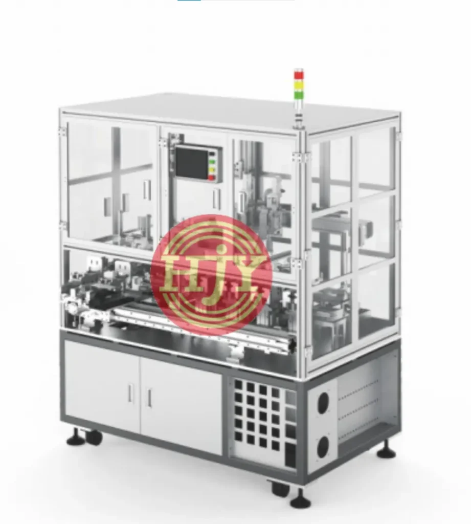
Depending on the winding structure, automatic loading, winding, preforming, thermal bonding, cylindrical forming, final sizing, inspection and unloading can be integrated into one machine or a complete production line.
For winding structures suitable for direct mandrel forming, the cup-shaped winding can be formed during the winding process. Diamond and other preformed-coil designs can use a multi-station system for individual coil winding, preforming, positioning, initial cylindrical forming, thermal bonding and final sizing.
Main Benefits of Automated Production
- Improved winding-path and tension stability
- Better dimensional and product consistency
- Reduced manual handling and intermediate transfer
- Higher production efficiency and equipment utilisation
- Process parameter recording and production traceability
- Improved yield in batch production
The highest possible level of automation is not necessarily the most suitable solution. The equipment configuration should be evaluated according to the winding structure, product dimensions, wire diameter, target capacity, changeover requirements and investment budget.
Automatic Loading → Precision Winding → Preforming → Cylindrical Forming → Thermal Bonding → Final Sizing → Inspection → Automatic Unloading
5. Applications and Development Trends
With their low rotational inertia, fast dynamic response, minimal cogging and smooth operation, coreless motors are particularly suitable for applications requiring compact dimensions, low weight, rapid response and precise motion.
Typical Applications
- Humanoid and biomimetic robot actuators
- Medical devices and miniature pumps
- Aerospace and aircraft actuation systems
- High-response servo systems
- Precision instruments and optical equipment
- Premium consumer electronics
- Automated gripping, positioning and miniature drive systems
As robotics, medical automation, unmanned systems and precision equipment continue to develop, coreless motors are moving toward smaller dimensions, higher power density, improved winding consistency and larger-scale automated production.
6. JHY Coreless Motor Automation Solutions
JHY provides customised coreless motor winding equipment and automated production line solutions based on the customer’s motor design, winding drawing, wire diameter, number of turns, winding structure and production target.
Scope of Our Solutions
- Straight, skewed and diamond coil winding
- Precision tension control for self-bonding enamelled wire
- Single-station and multi-station automatic winding
- Coil preforming, initial forming and final sizing
- Thermal bonding and cylindrical forming
- Automatic demoulding and unloading
- Resistance, turn-count and visual inspection
- Armature component assembly and downstream automation integration
From prototype development and small-batch manufacturing to mass production, JHY can configure the appropriate equipment functions and level of automation for the customer’s actual process requirements.
Start Evaluating Your Coreless Motor Project
For an accurate evaluation of the winding process, forming method, production cycle and automation configuration, customers are encouraged to provide the following information:
- Product and winding drawings
- Detailed winding-path drawings
- Enamelled wire diameter and material
- Number of turns and motor poles
- Winding structure and finished dimensions
- Product samples
- Target capacity and cycle-time requirements
- Upstream and downstream processes to be integrated
If you are developing a coreless motor or planning an automated production line, contact JHY. Our engineering team will evaluate a suitable winding process and automation solution based on your product and production requirements.